Dvm Wiring Diagram For 100

Dvm Wiring Diagrams For 100 Wiring Diagram List
Wrg 5531 Dvm Wiring Diagrams For 100
Vulink2 Digital Transmission System User Manual Digital Ally
Dvm 800 installation guide 860 00185 00 rev j digital ally inc.
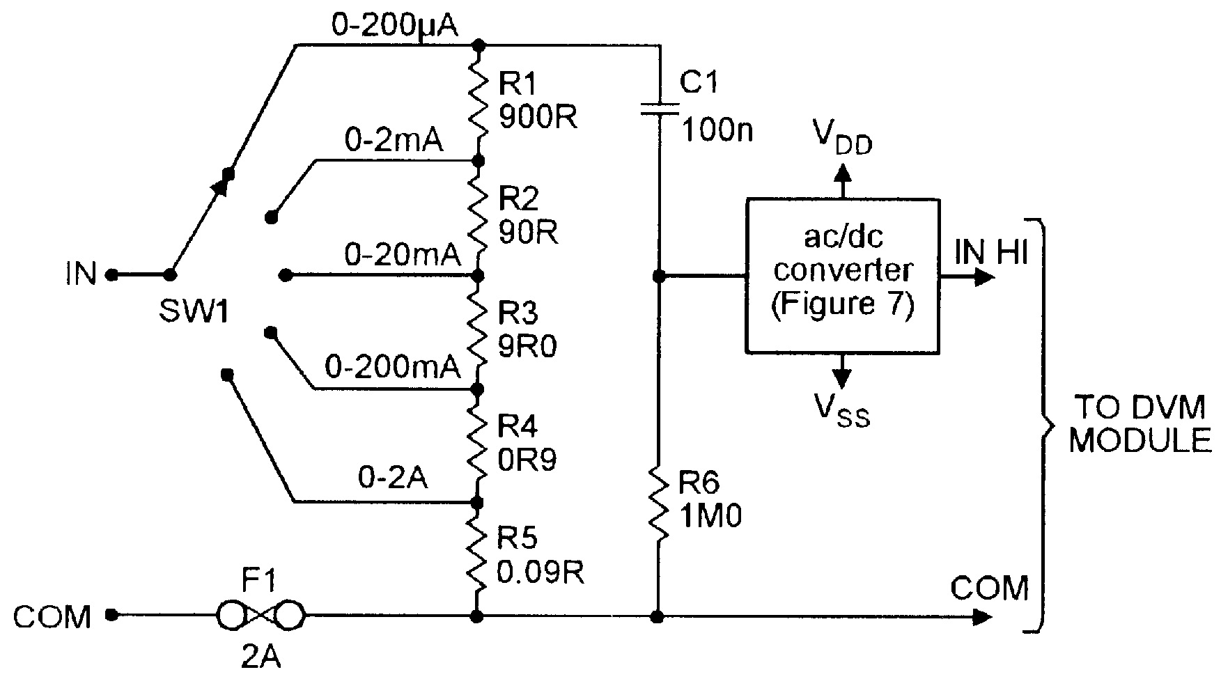
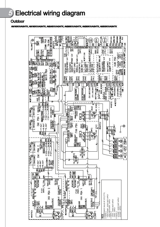
Dvm wiring diagram for 100. You need a wiring diagram with an external shunt instead. Vulink operation installation guide 860 00198 00 rev e digital ally inc. Dvm 500plus installation guide 002 0501 02 rev c page 3 standard limited warranty model dvm 500plus rear view mirror in vehicle digital video system we warranty that our in car digital video system model dvm 500plus will be free from defects in. The system will also provide the control and electrical wiring diagram generate a wiring diagram for selected central control options and delivers a print.
Records audio from the passenger compartment. Camera installation dvm 400 only 14. Also when measuring current that exceeds 10a which can be handled with the internal one. View and download digital ally dvm 100 installation manual online.
Parts ables and accessories 2 1 section 2. Used for viewing video. Dvm 100 dvm 400 installation guide 860 00187 00 rev digital ally inc. Digital in vehicle event recorder video system.
Dvm 100 dvr pdf manual download. Model specific wiring diagrams dvm 100 dvm 400 lue orange dvm vulink ase able 008 01456 00 lak hassis ground dwm wireless microphone able n 12vd switched ignition red 12vd attery fused. I nstallation dvm 400 o nly 14. Dvm 100 wiring diagram 6.
I am wanting to insert this dvm into several power supplies none. Factory mirror removal 10. How to wire digital dual display volt and ammeter. Dvm 400 wiring diagram 9.
Parts lists and system diagrams 2 4 dvm layout configuration 1 l d display. Samsungs dvm pro system design software is an advanced design selection tool that helps users select the most appropriate vrf or chiller equipment based on the information provided. So ive put together a diagram attached below detailing what im calling dvms full boat dual humbucker wiring mod. Digital ally dvm 100 manuals.
Basic seriesparallel wiring the diagram at right shows the wiring for a dpdt pp that switches between a series and parallel orientation of the two coilsit is significantly more complicated that the coil cut using five of the switchs six contacts. I understood the max rating of the dvm in relation to the power source. Model specific wiring diagrams 3 1 section 3. From the various mods ive made to my epiphone dots humbucker wiring i now realize what i should have done to start with.
When in the up position as indicated in the diagram the two coils will be connected in parallel.
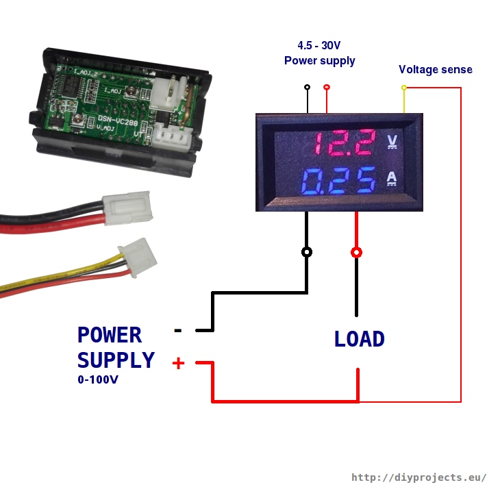
How To Wire Digital Dual Display Volt And Ammeter Diy
Vulink2 Digital Transmission System User Manual Digital Ally
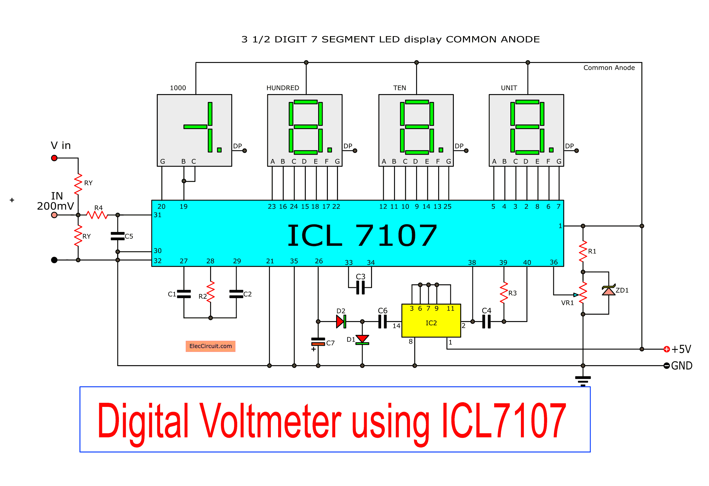
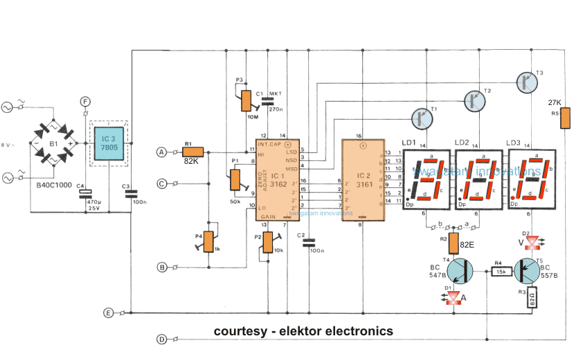
Digital Voltmeter Circuit Diagram Using Icl7107 7106 With Pcb
Digital Ally Dvm 100 Manuals

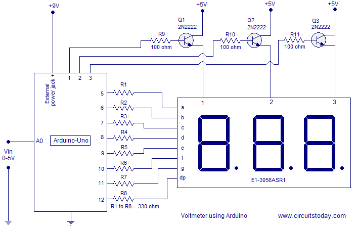
Digital Arduino Voltmeter 0v 12v 30v

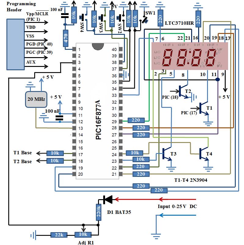
Digital Voltmeter With 3 Digit Output By Pic16f676 Eeweb
Simple 0 5v Three Digit Voltmeter Using Arduino 50mv
Simple Digital Voltmeter Microcontroller Based Projects
Vulink1 Digital Transmission System 2400 2483 5 Mhz User

Wiring Pre Circuit Diagram Floating 9v Supply For Dvm Modules
How To Make A Digital Voltmeter Ammeter Module Circuits

Dvm S Water Service Manual Manualzz Com
Pic Based Digital Voltmeter Dvm Embedded Lab

Dvm Wiring Diagrams For 100 Wiring Schematic Diagram 43
Chinese Electronics Products Tested Dsn Dvm 368 Digital

Simple Digital Voltmeter Circuit With Pcb Using Icl7107

Digital Ally Dvm 250 Wiring Diagram Digital Ally Dvm 500
Vulink1 Digital Transmission System 2400 2483 5 Mhz User
