High Power Subwoofer Amplifier Circuit Diagram

1500 Watt High Power Amplifier Amp Circuit Diagram In 2019

Tda7294 Subwoofer Amplifier Circuit
100w Subwoofer Amplifier Circuit Diagram Working And

This tda2030 amplifier can produce 14watt output and this can be increased upto 30watt by using another tda2030.
High power subwoofer amplifier circuit diagram. See more ideas about circuit audio amplifier and circuit diagram. You can choose 05w to 1200w. Related post 100w subwoofer amplifier circuit. In this project we are going to design a subwoofer amplifier circuit using ic tda2030 with few cheap components.
Subwoofer pre amp filter circuit acoustic spectrum is extended by the 20hz frequency is very low and reaches as high frequency 20000hz. Subwoofer amplifier circuit principle. 105watt at 4 ohm load 88watt at 8 ohms load. The initial subwoofer amplifier had been engineered in 1970 by ken kreisler.
So easy to builds. So if the stereo high power amplifier 2 x 1400w power output 2800w. If subwoofer in your music system is not producing enough bass then you can use this simple diy circuit to enhance the bass. Many power amplifier circuit diagram with pcb layout.
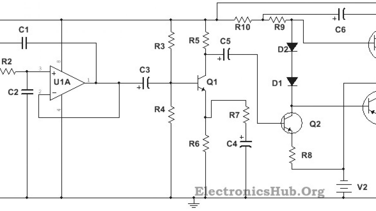
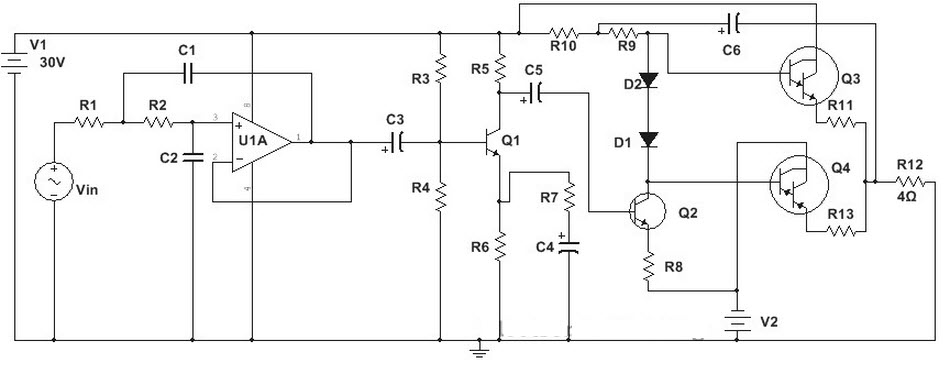
The post explains a simple high power subwoofer amplifier circuit which could be used for driving high bass subwoofer speakers and home theater systems. This circuit is theoretical and the output contains. This low power signal is then amplified using a transistor driven class ab power amplifier. This power amp ocl 100 watt circuit by transistorsthey has been an old circuits but very well amplifier schematic.
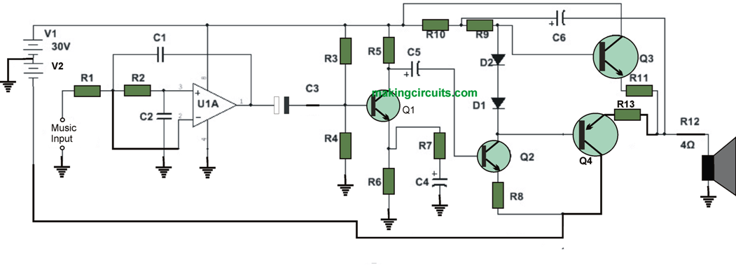
Using transistors mosfet ic on a lot types. This low frequency signal is then amplified using a voltage amplifier. Power amplifier circuit diagram is still less by looking at the circuit that was so below the finished circuit has been added with gains using two jrc4558 ic the picture ic where it can be seen below. It is designed for intermittent duty suitable for an equalized sub woofer system for example using the elf principle see the project page for the info on this circuit.
Follow stye of ocl amp and they has specification are power output. We can also use this circuit to drive high power antennas for long range transmission. This circuit can be used to drive a loudspeaker of low input impedance in audio amplification. Making it to you we propose to distinguish these frequencies in order for him to lead us on a suitable amplifier.
In the low frequency is lowered sense of direction. Audio signal is first filtered to remove the high frequency signals and allow only the low frequency signals to pass through it. This reasoning leads us to attribute to the speakers use of very low frequency. For circuit buffers drivers and booster use multiple transistors and.
Applications of power amplifier circuit. A subwoofer is actually a loudspeaker which will develop audio signals of lower frequencies.

Subwoofer Booster Circuit With Pcb Layout In 2019 Circuit

300 500w Subwoofer Power Amplifier

1500 Watt High Power Amplifier In 2019 Stereo Amplifier
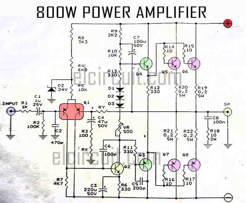
800w Power Amplifier Circuit Electronic Circuit

Power Amplifier Audio Circuit High Power Amplifier
Build A 300 Watt Subwoofer Power Amplifier Circuit Diagram
Subwoofer Amplifier Circuit High Power
100w Subwoofer Amplifier Circuit And Applications
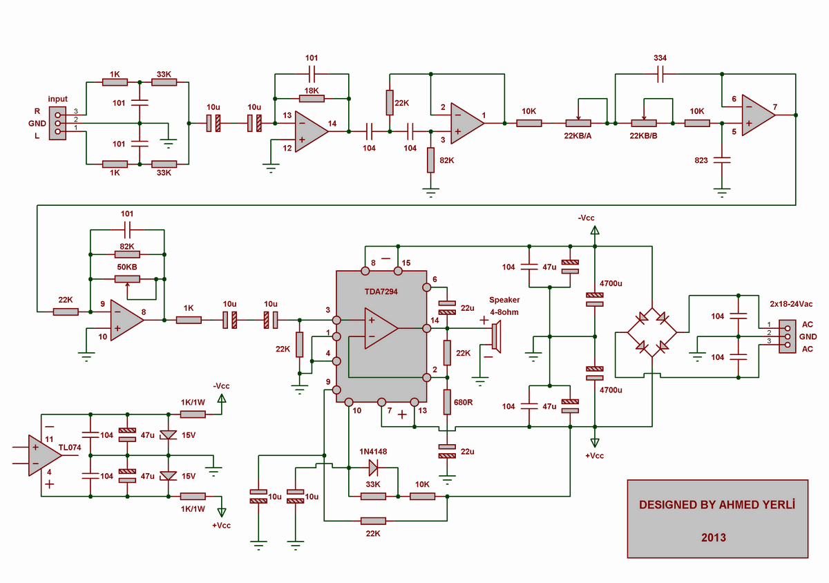
Siwire Tda7294 Subwoofer Schematic
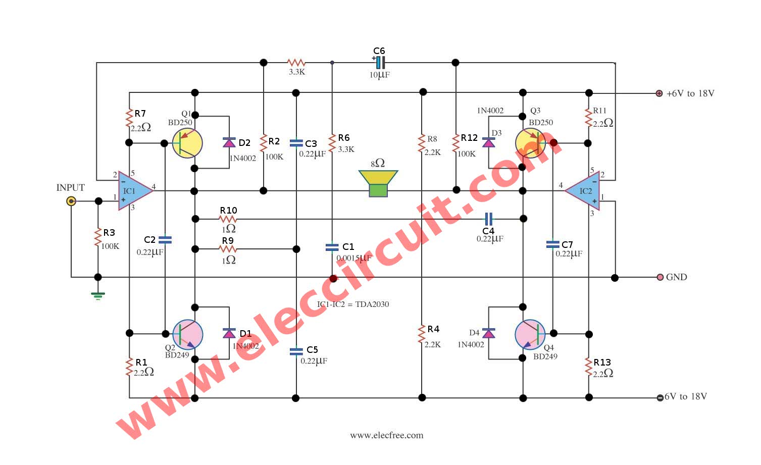
Tda2030 Subwoofer Amplifier Circuit Eleccircuit Com

100 Watt Power Amplifier Circuit Diagram Using Mosfet

121 Best Power Subwoofer Circuits Images In 2019 Powered
300 500w Subwoofer Power Amplifier

Tda2030 Audio Amplifier Circuits Eleccircuit Com
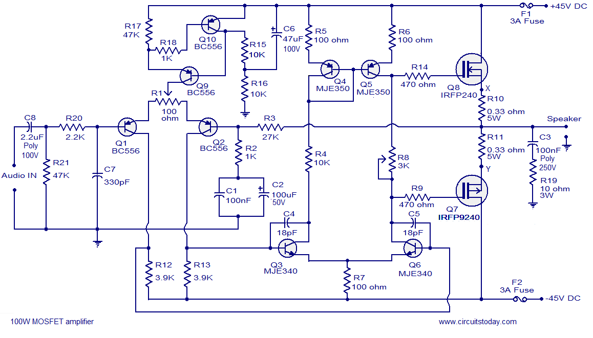
100w Mosfet Power Amplifier Circuit Using Irfp240 Irfp9240
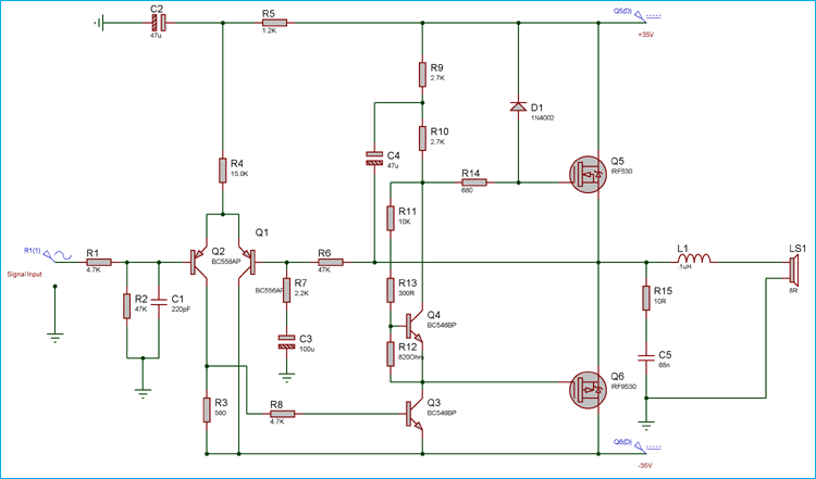
50 Watt Power Amplifier Circuit Diagram Using Mosfets
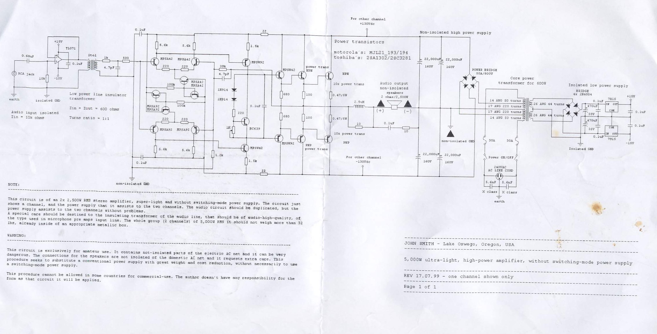
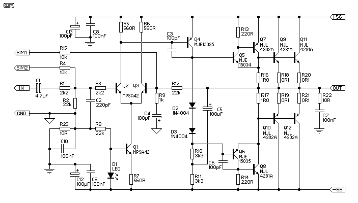
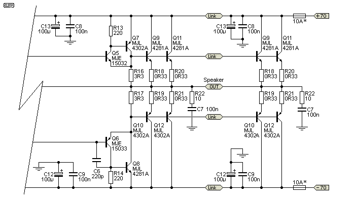
5000w Ultra Light High Power Amplifier Electronics Lab

4558 Ic Circuit Diagram Audio Power Amplifier Amplifier
