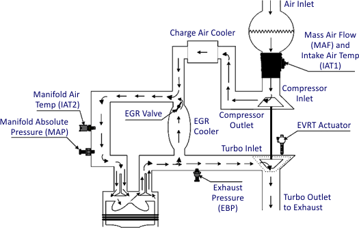
Engine Intake Exhaust Flow Diagram
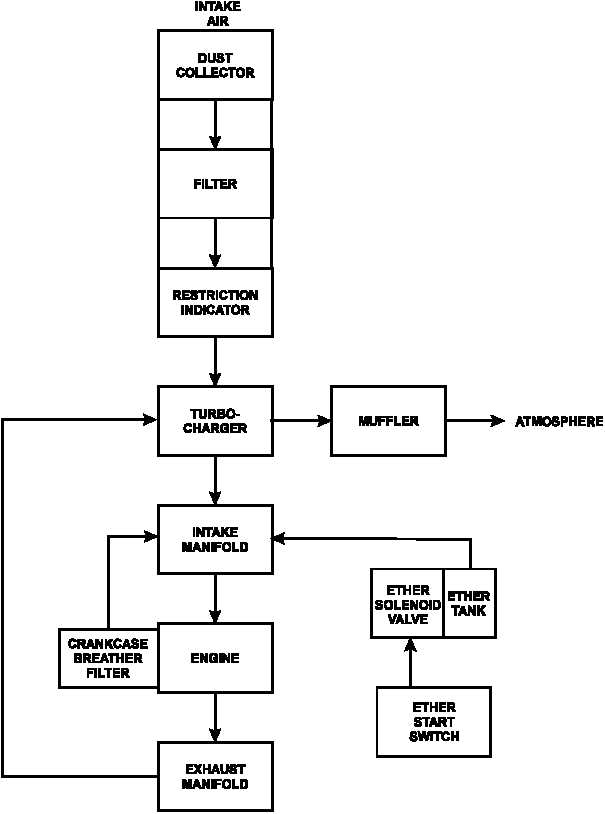
Figure 1 26 Engine Air Intake And Exhaust System Flow

3 Diesel Engine Flow Diagram Download Scientific Diagram

Diesel Engine Flow Diagram The Subscripts A C I

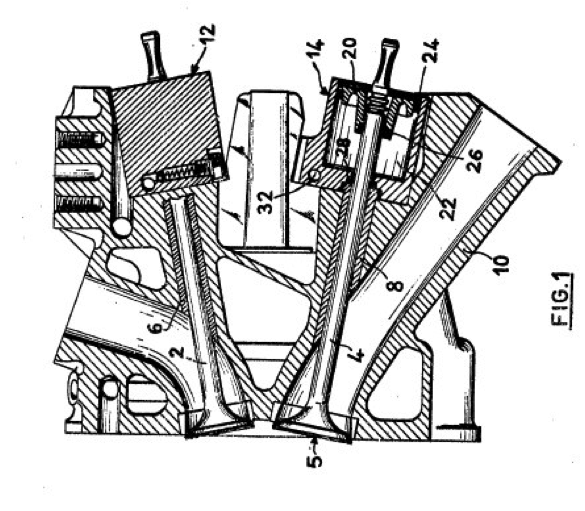
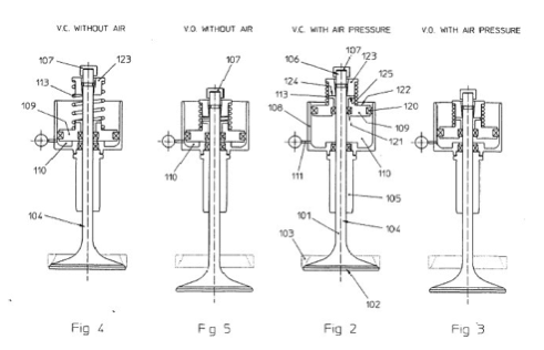
Engine intake and exhaust valve basics.
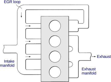
Engine intake exhaust flow diagram. The right blue side is the intake port and the left brown side is the exhaust port. Cold air intake basics. 4 stroke engine diagram. The flow diagrams shown are different from mine as they show two hoses from the intake raw water one leading to the stat and one going to the pump for the exhaust maniflods where mine on the 318 only has the one raw water inlet which divides at the stat housing for the exhaust manifolds and the engine.
That air is used to help ignite the fuel which will drive the pistons up and down. Exhaust design and flow. Pumping losses refer to the amount of horsepower hp used to push the exhaust gases out of the cylinders on the engines exhaust stroke. As noted in our review of rush the mae designation stood for modified anglia engine and as seen in the accompanying photos the intake and exhaust ports are on the same side of the cylinder headthis is not an unusual port arrangementas its quite common in many i4 and straight 6 applications but cosworth redirected the intake port or stood it up to give the airflow a more.
The main function of the engine valves is to let air in and out of the cylinders. Accurate air flow measurements through cylinder heads intake and exhaust manifolds intake air cleaner boxes throttle bodies exhaust piping systems mufflers and catalytic converters would be used to develop more efficient engines and improve computer engine models. In an internal combustion engine scavenging is the process of replacing the exhaust gas in a cylinder with the fresh airfuel mixture or fresh air in the case of direct injection engines for the next cycle. Simple intake manifolds move intake air along the shortest route while more complex versions may direct air along a more circuitous route or even multiple routes depending on engine speed and load.
Since less hp is used to get the exhaust out of the engine more horsepower is available at the flywheel. Intake and exhaust valves. However two difficulties arise for these intakes. Controlling air flow this way can make for more power or efficiency depending on demand.
Four stroke cycle used in gasolinepetrol engines. If scavenging is incomplete the remaining exhaust gases can cause improper combustion for the next cycle leading to reduced power output. What is a fuel injector. The cylinder wall is a thin sleeve surrounding the piston head which creates a space for the combustion of fuel and the genesis of mechanical energy.
Engine valves are located in the cylinder head. Intake 1 compression 2 power 3 and exhaust 4. There are two types of engine valves. This intake is known as a mixed compression inlet.
Horsepower and torque explained engine oil cooler design and installation. When these components are modified to increase flow out of the engine pumping losses are reduced. Engine oil weights viscocity.

Schematic Picture Of The Air Intake System Download

Figure 1 From Characteristics Of K3 Vei4 Engine Performance
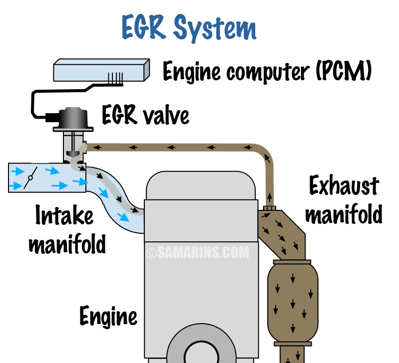
How Exhaust Gas Recirculation Egr System Works
Engine Intake And Exhaust Valve Basics Location Function
Valves And Ports In Four Stroke Engines
Egr Control Strategy

Block Diagram Of A Naturally Aspirated Si Engine Download

Valve Timing And Duration Engineknowhow
Engine Intake And Exhaust Valve Basics Location Function

Exhaust Gas Recirculation Egr W220 S Class Encyclopedia

Diesel Engine Air Exhaust Flow Youtube
Envirovent Ccv Kit 6cta 8 3 Qsl 9 Series
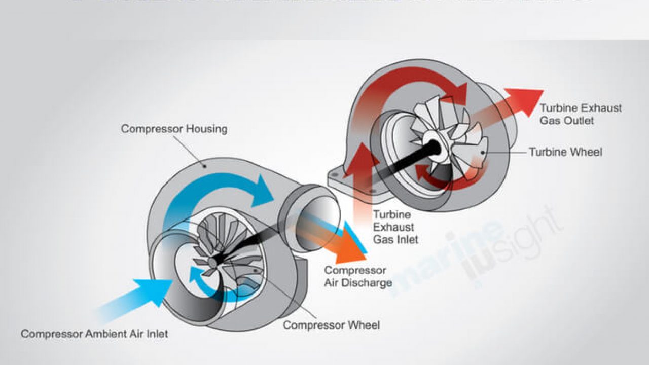
What Is Turbocharger Surging

Fuel Intake How Two Stroke Engines Work Howstuffworks
Exhaust Gas Recirculation

Intake Manifold Pressure And Exhaust Gas Recirculation

Schematic Picture Of The Air Intake System Download
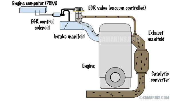
How Exhaust Gas Recirculation Egr System Works
