Wiring Diagram For Radon Fan

Pt2 Pre Wired Low Voltage Radon System
Hvacquick How To S Wiring 1 Fan Serving 2 Baths With 1

Ceiling Fan Wiring Diagram Kingofprussiadoulas Co

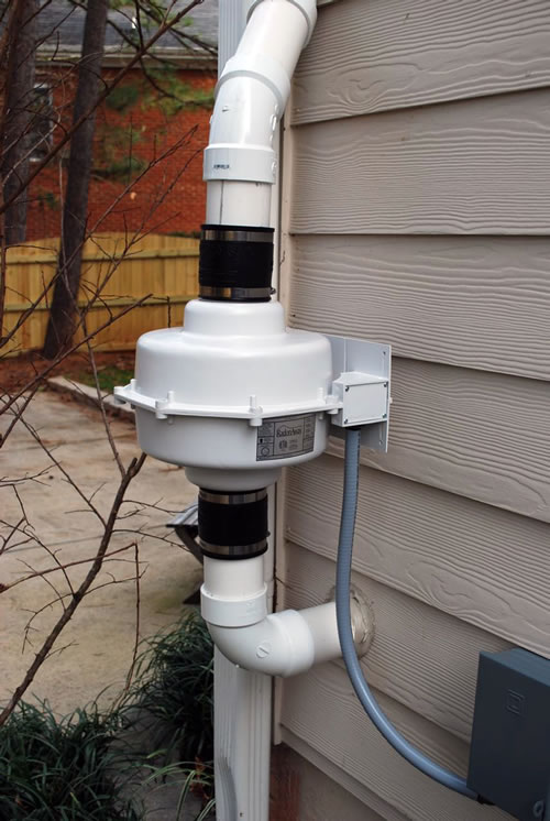
I used thhn wiring inside conduit and hardwired it to the electrical box.
Wiring diagram for radon fan. 14 717 3 ay ar 1835 adonaway. For optimal removal of radon or other vocs other contaminants such as iron or. During entire warranty period. The removal of radon and some other vocs.
I agree with the others that it is easy to replace a radon fan. I installed the entire radon system in my house last year. The purpose of these instructions is to provide additional guidance for the most effective use of gpgpc. There is a light extremely close to where i need power so im considering tapping at that location.
Do not use this fan with any solid state speed control device. Gpgpc xpxpc xr series fan wiring diagram. The source is at the switches and the input of each is spliced to the black source wire with a wire nut. These diagrams are current at the time of publication check the wiring diagram supplied with the motor.
The aeration process employed by the airaider. Installation instructions for radon fans model hpfr warnings do not connect power supply until fan is completely installed make sure electrical service to the fan is locked in off. I have a question about mixing wire size. Just order a new fan shut off electrical to the fan put new fan on turn electrical back on.
This wiring diagram illustrates the connections for a ceiling fan and light with two switches a speed controller for the fan and a dimmer for the lights. Im installing a radon fan and need to tap into an existing circuit to supply power to the fan. The gpgpc xpxpc and xr series radon fans are intended for use by trained professional certifiedlicensed radon mitigators. Ceiling fan with light kit wiring diagram.
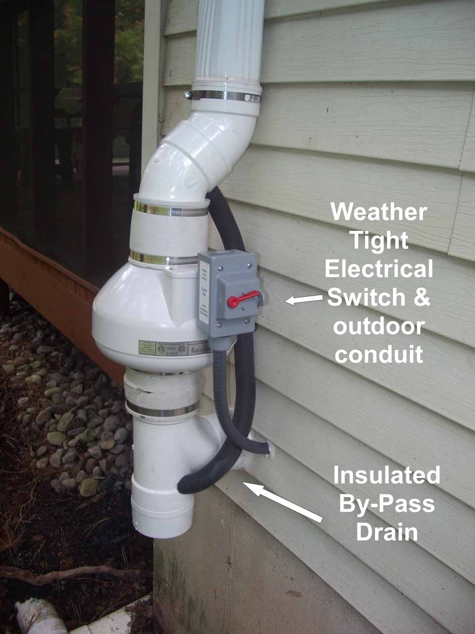
I put an outdoor approved switch next to the fan outside. Radon fans draw very little amps so they could be tapped to an existing circuit but life saving equipment is suppose to be on a dedicated circuit. Gpgpc xpxpc xr series fans. 3o wiring diagrams 1o wiring diagrams diagram er9 m 3 1 5 9 3 7 11 low speed high speed u1 v1 w1 w2 u2 v2 tk tk thermal overloads two speed stardelta motor switch m 3 0 10v 20v 415v ac 4 20ma outp uts diagram ic2 m 1 240v ac 0 10v outp ut diagram ic3 m 1 0 10v 4 20ma 240v ac outp uts these diagrams are current at the time of publication.
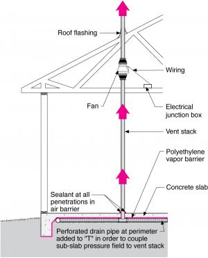
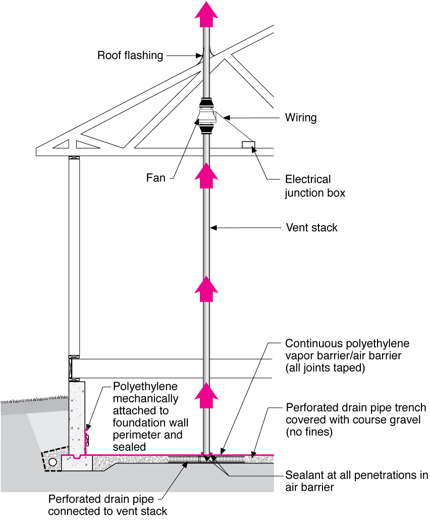
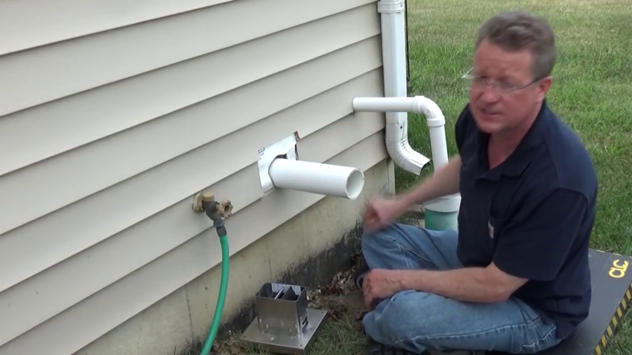
Prior to installation the suction pipe should be terminated at the exterior wall. System and other radon removal systems can worsen problems due to iron or manganese contaminants in the water supply. Category howto style. Suitable for use with solid state speed control.

How To Wire Outdoor Radon Fan Doityourself Com Community

Radon Fan Connection Google Search Electrical Wiring Fan
Hvacquick How To S Radon Mitigation

A Typical Radon Mitigation System Image From Building
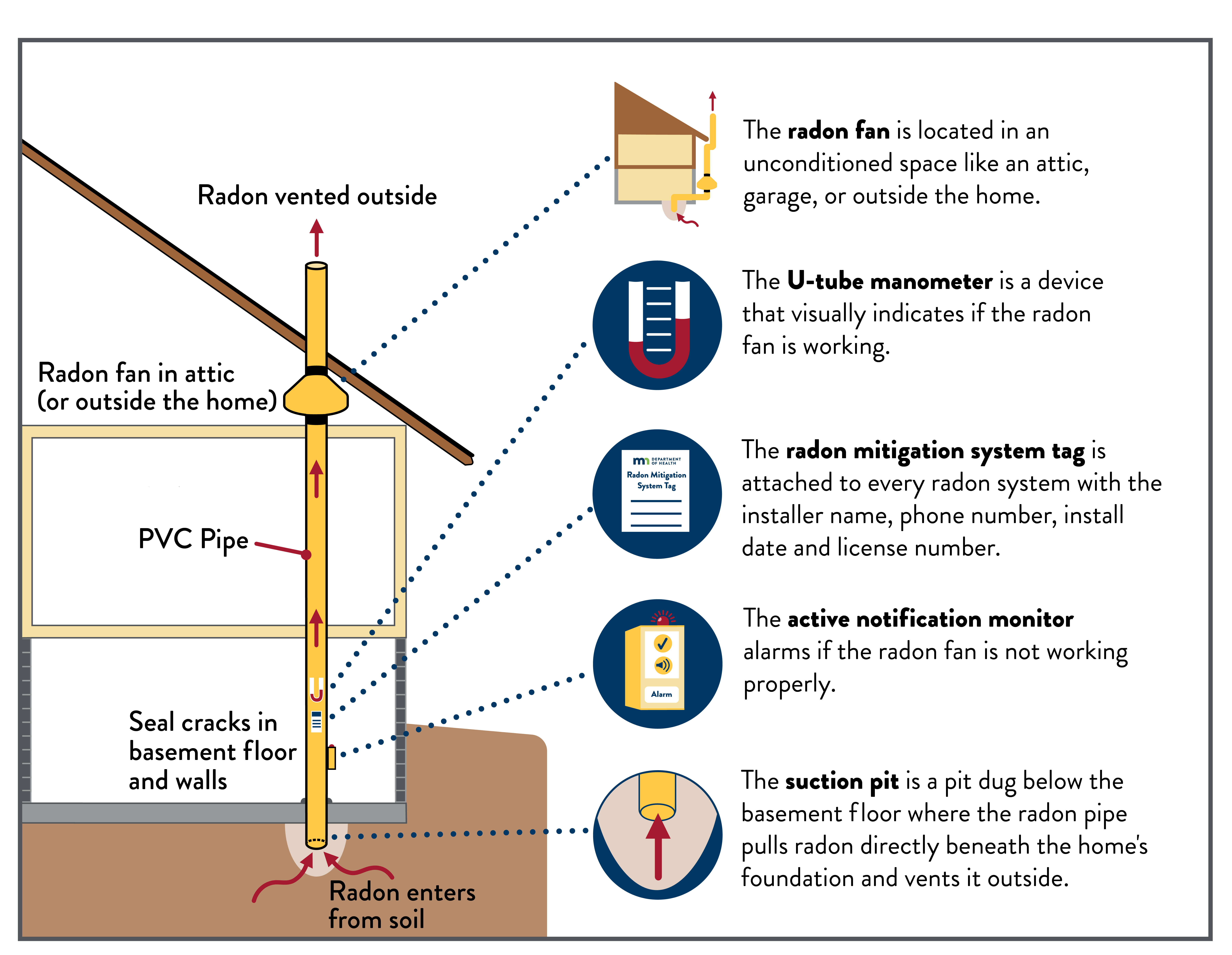
Radon Mitigation System Eh Minnesota Department Of Health
Radon Mitigation Installation Tips For Radon Installers And

Ceiling Fan Wiring Diagram Kingofprussiadoulas Co
Radon Fan Installation Photos Radonaway
Radon Fan Building America Solution Center
Radon Mitigation Photos Of Radon Remediation System

Athelonenterprises Com Radon Mitigation
Radon Fan Building America Solution Center
Radon Fan Installation
Infiltec Radon Gas Mitigation System Drawings
Radon Mitigation Installation Tips For Radon Installers And

New Construction Smarts Radon Mitigation Systems Ideas

Suncourt Radon Fan Mitigation Kit Rdk04 3 Suncourt Inc

Radon Fan Menards Taikus Co
