Step Up Chopper Diagram
Step Up Chopper Dc Dc Converter Chopper Electronics Tutorial

Step Up Choppers ह न द

Working Of Step Up Chopper Electrical Revolution

The diagram below shows a buck boost chopper.
Step up chopper diagram. It is a class of switched mode power supply smps containing at least two semiconductors a diode and a transistor and at least one energy storage element. A capacitor inductor or the two in combination. Step up chopper works as a step up transformer on dc current. Essentially a chopper is an electronic switch that is used to interrupt one signal under the control of another.
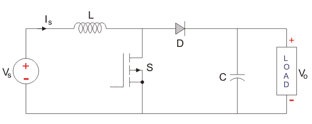
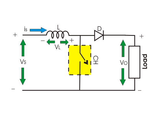
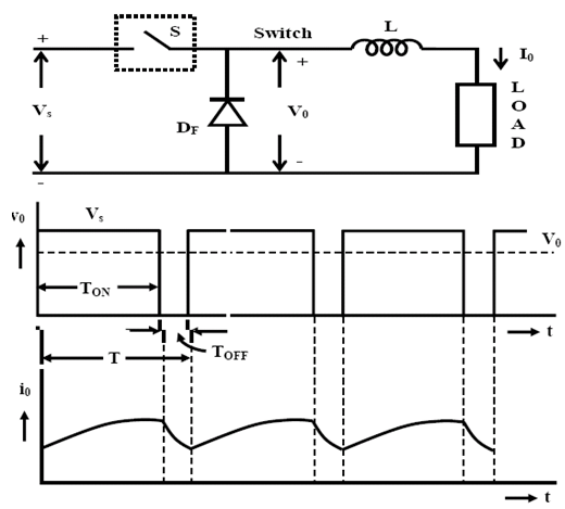
This kind of choppers are more efficient as they involve one stage conversion. Figure below shows the circuit diagram and waveform of step up chopper. As shown in the circuit diagram in this chopper a large inductorl in series with the source voltage v s is essential to get the voltage higher than the supply voltage. This is also known as a buck boost converter.
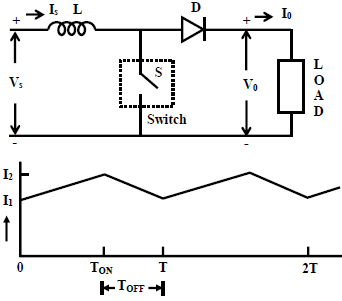
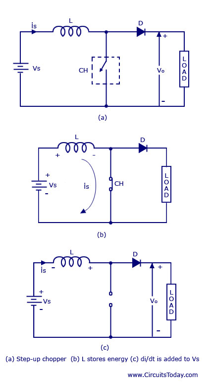
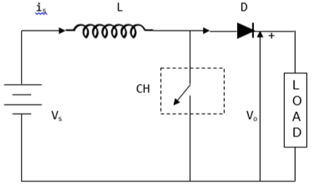
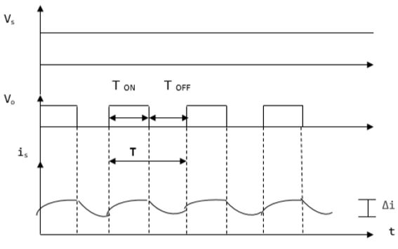
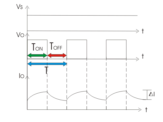
The basic diagram for the step up chopper is shown in the figure a. Operation of step up chopper. The average load voltage of the chopper can be given by. When the chopper is switched on during ton time the energy stored in the inductor via path vdc l.
A chopper can be said as dc equivalent of an ac transformer as they behave in an identical manner. Just like a transformer a chopper can be used to step up or step down the fixed dc output voltage. A boost converter step up converter is a dc to dc power converter that steps up voltage while stepping down current from its input supply to its output load. The direction of.
Step up chopper or boost converter is used to increase the input voltage level of its output side. When the chopper is switched on the inductor l becomes charged by the source voltage v s. Stepupchopper procedures step 1 precautions. Its circuit diagram and waveforms are shown below in figure.
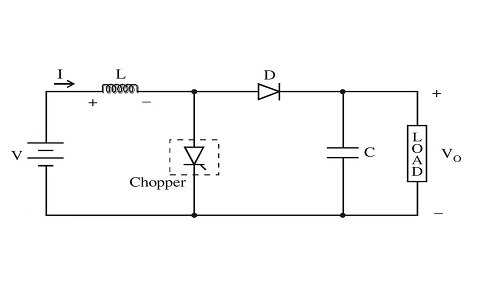
In the circuit a large inductor l is connected in series to the supply voltage. A step up chopper is used to obtain a load voltage higher than the input voltage v. The working principle of a step up chopper can be explained from the above diagram. It makes it possible to increase or reduce the voltage input level.
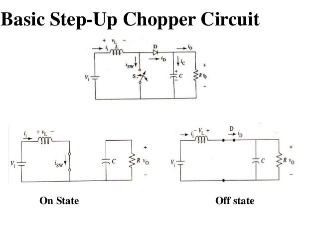
Step up chopper the step up chopper is one in which output dc voltage is greater than the input dc voltage. A step up chopper provides a minimum output voltage equal to the dc supply voltage and the output voltage higher than dc input can be obtained. A when the chopper is on the inductor l is connected across the supply. A the values of l and c are chosen depending upon the requirement of output voltage and current.
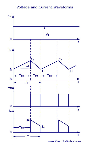
Where a is the duty cycle the ideal waveform of the experimental setup is shown in figure below. Step up step down chopper. This chopper is used when the output dc voltage has to be made higher than the input voltage. A main switch should be included in whole circuit so that in.
Boost Converter Step Up Chopper Electrical4u

Difference Between Step Up Chopper Vs Step Down Chopper
Chopper Circuit Working Principle Types And Applications
Choppers And Types Ac And Dc Chopper Circuits

Engineering Notes Step Up Down Choppers Engineering Notes

Subject Power Electronics 1 Topic Step Down Step Up
Power Electronics Choppers Tutorialspoint
Chopper Dc To Dc Converter Electrical4u

Difference Between Step Up Chopper Vs Step Down Chopper

Working Of The Step Up Step Down Chopper Electrical

Introduction Of Step Up And Step Down Chopper
Choppers And Types Ac And Dc Chopper Circuits
Chopper Operation

10 Step Up Chopper Circuit Download Scientific Diagram
Power Electronics Choppers Tutorialspoint
Chopper Dc To Dc Converter Electrical4u
Step Down Chopper Dc Dc Converter Chopper Electronics
Step Up And Step Down Mosfet Based Chopper Nss Eng College
