Step Dimming Ballast Wiring Diagram

T8 4 Lamp Ballast Wiring Diagram 4 Lamp T8 Ballast Wiring
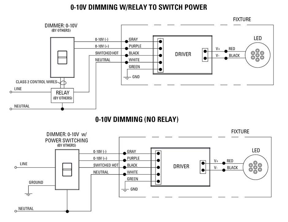
Low Voltage Led 0 10v Dimming Usai

Dimming Ballast Wiring Diagram Wiring Schematic Diagram
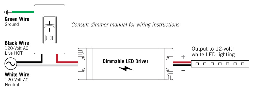
Our standard 0 10v dimming driver option is often provided standard check spec sheets and dims down to 10 at minimum light level.
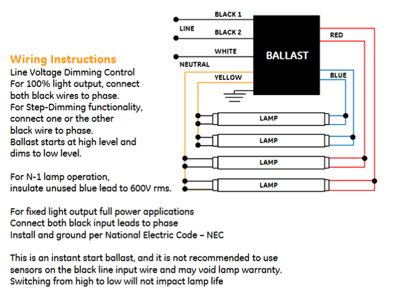
Step dimming ballast wiring diagram. 3 way switch wiring diagram 0 10v dimmer electric switches the wall switch single pole switch double pole switch three way switch basics of 3 way switches wiring a line of heavy industrial series wiring devices legrand launches harmony 174 when you are using 0 10v led drivers in order to make sure your. Proceed to step 5. These ballasts use two line voltage switches for selecting operation at full intensity or at half power. Ge ultramax ballasts provide a wide variety t8 step dimming ballast.
Replaced with rapid start sockets to allow proper dimmer operation and prevent damage to the dimming ballast. Application note 28 appendix b. Step dimming ballasts are relatively inexpensive and often used with occupancyvacancy sensors or automatic timers to optimize energy usage. Refer to the instructions provided with the ballast.
A 0 10v dimmer is considered analog dimming and all usai 0 10v dimming options are considered to be sink type dimming. 13 sockets and lampholders 16 lamp wiring diagrams 19 ballast control types 20 ecosystem ballasts 22 emergency backup ballast 24 ballast troubleshooting 25 installation best practices 26 appendix a. Fluorescent dimming systems technical guide 02 lutron fluorescent dimming ballasts 04 how it works 05 lamp. Electrically connect the sensor to the lighting system per the applicable wiring diagram on page 4.
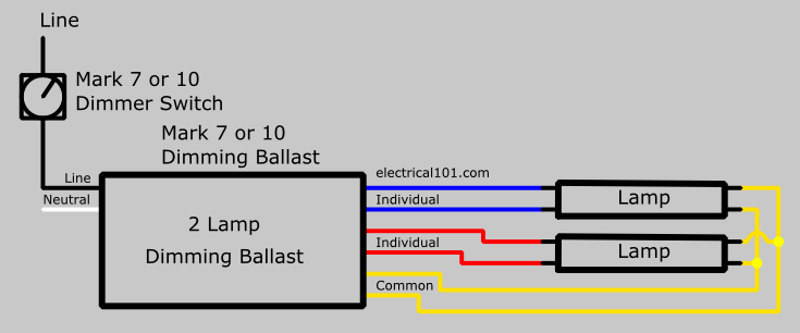
2 lamp dimming ballast wiring diagram. 0 10v or 4 wire dimming ballasts provide continuous light output typically 5 to 100 based on the input voltage of the 0 10v line. Step dimming ballast wiring diagram. Dimming ballasts are available for fluorescent tubes and cfls that use an external ballast.
0 10v dimming wiring diagram 0 10v dimmer switch leviton ip710 lfz or equal for other types of dimming control systems consult controls manufacturer for wiring instructions switched hot black switched hot red typical low voltage dimming wires purple gray typical electrical panel hot black typical 120v or 277v 60 hz neutral white. Using advance mark 7 or mark 10 dimming ballast and dimmer switch. The switches will turn the light on at the brightness level. Use only one 1 dimmer in a 3 or 4 way circuit.
Connect wires per wiring diagram as follows. These ballasts are usually rapid start or programmed start and have a good dimming range. 2 lamp series ballast wiring. Attach sensor to fixture or electrical box using the 2 8.
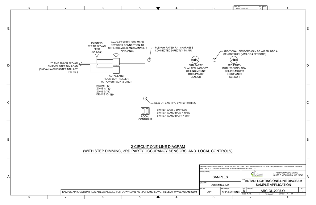
Step dimming control facilitates energy code compliance without installation of low voltage control wiring. Occupancy sensor with 0 10v dimming control installation instructions. The levelpro family of ballasts is designed for maximum energy savings and high efficiency and they are cee compliant. By offering two or three lighting levels step dimming ballasts used with occupancy sensors can reduce light output without resorting to onoff cycling of lamp operation which usually results in an appreciable reduction in lamp life.

Dimming Ballast Wiring Diagram Abeauvilliers Com

Step Dimmer Bathroom Fan And Dimmer Switch Installing A Bath
Dimmable Ballast Wiring Diagram Wiring Schematic Diagram

Dimmable Ballast Wiring Diagram Wiring Diagram
H Moss Occupancy Sensors H Moss

Mark 7 Ballast Wiring Diagram Wiring Schematic Diagram

Step Dimming Ballast Wiring Diagram Wiring Diagram Echo
2 Circuit One Line Diagram With Step Dimming 3rd Party

Wrg 0912 Led With Dimmer Wiring Diagram

71497 Ge Lfl Ultramax Step Dimming Electronic Dimming
Ge Stepped Dimming Ballast Wiring Diagram Wiring Diagram

How To Bypass A Ballast 1000bulbs Com

Optotronic Step Dim Programmable Led Drivers Digital Systems

Switch Wiring Diagram Pdf Single Phase Motor New Engine
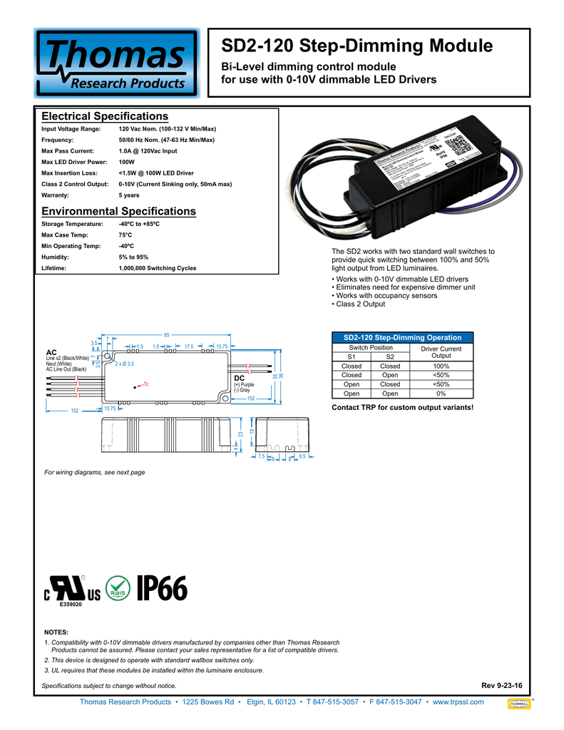
Sd2 120 Step Dimming Module
Ge432max90 S60 73229 Ge Ultramax Ballasts 100 60 Bi Level Dimming

The Dim State Of Affairs Electrical Contractor Magazine

How Do Dimming Sensor Of Led High Bay Works Fireflier
