Schematic Circuit Diagram

Circuit Diagram Wikipedia
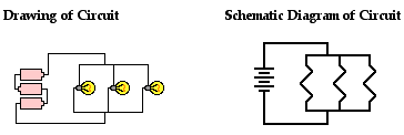
Difference Between Schematics And Circuit Diagrams
Difference Between Schematics And Circuit Diagrams

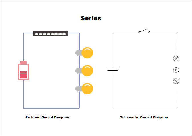
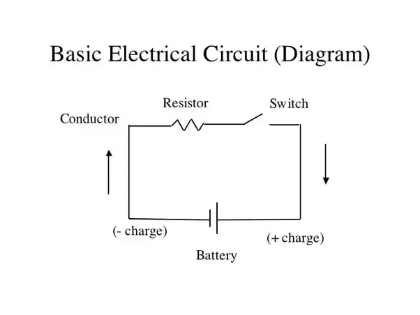
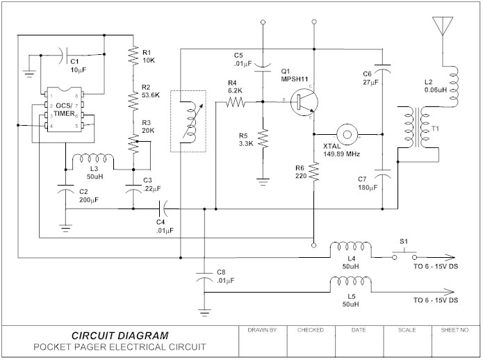
Circuit diagrams or schematic diagrams show electrical connections of wires or conductors by using a node as shown in the image below.
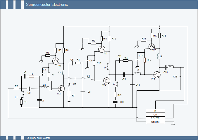
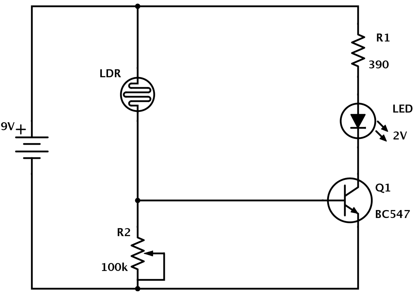
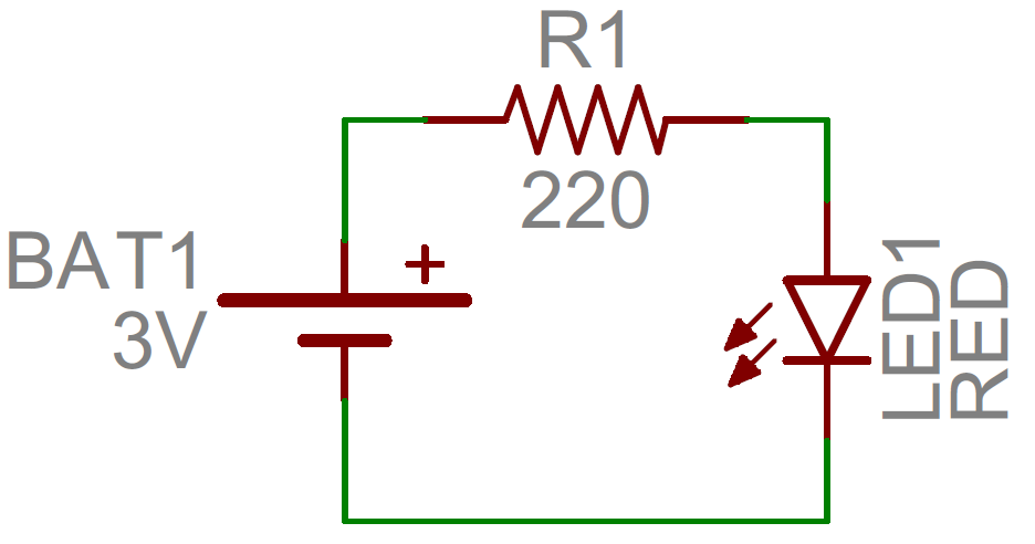
Schematic circuit diagram. A circuit diagram electrical diagram elementary diagram electronic schematic is a graphical representation of an electrical circuit. When three or more lines touch each other or cross each other and a node is placed at the intersection this represents the lines or wires being electrically connected at that point. In a schematic circuit diagram the presentation of electrical components and wiring does not completely correspond to the physical arrangements in the real device. Design circuits online in your browser or using the desktop application.
The presentation of the interconnections between circuit components in the schematic diagram does not necessarily correspond to the physical arrangements in the finished. Schematic symbols for an atmega328 microcontroller commonly found on arduinos an atsha204 encryption ic and an attiny45 mcu. Circuit diagram is a free application for making electronic circuit diagrams and exporting them as images. A pictorial circuit diagram uses simple images of components while a schematic diagram shows the components and interconnections of the circuit using standardized symbolic representations.
As you can see these components greatly vary in size and pin counts. A schematic circuit diagram represents the electrical system in the form of a diagram that shows the main features or relationships but not the details. For example in a schematic diagram depicting an electrical circuit you can see how the wires and components are connected together but not photographs of the circuit itself.
How To Read A Schematic Learn Sparkfun Com

What Is The Difference Between Schematic Diagram And Wiring
What Is The Difference Between Circuit Diagram And Schematic
Difference Between Schematics And Circuit Diagrams
Circuit Diagram How To Read And Understand Any Schematic

Schematics Com Free Online Schematic Drawing Tool
How To Read A Schematic Learn Sparkfun Com

Circuit Diagram Wikipedia
Circuit Diagram Learn Everything About Circuit Diagrams

Electrical Diagrams And Schematics Wiki Odesie By Tech

Schematics Com Free Online Schematic Drawing Tool

How To Read A Schematic Learn Sparkfun Com
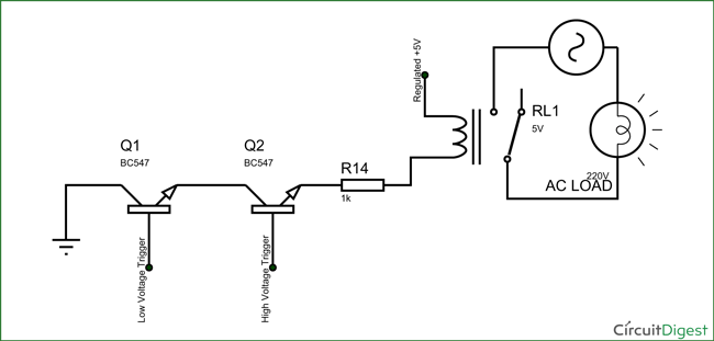
Electronic Circuit Breaker Schematic Diagram
The Physics Classroom Tutorial
How To Draw Schematic Diagrams

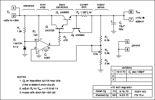
Schematic Circuit Diagram Of The Relaxation Oscillator

Schematic Wikipedia

Schematics Com Free Online Schematic Drawing Tool
