Piping Diagram Ac

Marine Accommodation Air Conditioner Piping Diagram
A Simple Air Conditioning Circuit And Cycle Diagram That You

Wrg 7297 Piping Diagram Ac

Use copper pipe with 10 mm or more thickness for o159 mm.
Piping diagram ac. You can also view the 2 modes showing the refrigerant states with buttons 4 and 5. Keep in mind that as the title of these posts says basic air conditioning piping recommendations. Two pipe originated 50 or 60 years ago as a cost effective way to add air conditioning. Learn from the experts at standard heating.
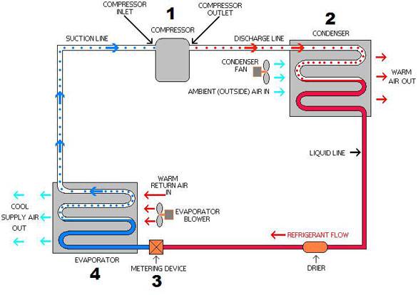
Hopefully the charts ive included will help as a service tool to see if the line set is a possible issue with a particular installation giving you problems. The red dots inside the piping represent discharge vapor. The diagram below shows a heat pump piping layout. It is one of the most often overlooked parts of the air conditioning system.
A 2 pipe hvac system is one that uses the same piping alternately for hot water heating and chilled water cooling as opposed to a 4 pipe system that uses separate lines for hot and chilled water. In fact it employs the same types of components materials and systems as a refrigerator including a refrigerant that changes from liquid to gas and back to liquid as it travels through a system of tubes and coils or fins that collect and give off heat. If you have to make plumbing repairs around your home it helps to understand your drain waste vent system dwv. A piping and instrumentation diagram pid is a detailed diagram in the process industry which shows the piping and process equipment together with the instrumentation and control devices.
Take out the flare nut attached to the air conditioner and. Click back and forth between buttons 2 and 3 and note how the discharge from the compressor is diverted to different coils in each mode. A central air conditioner is like a giant refrigerator for your house. The component at 2 in this air conditioning circuit and cycle diagram is the condenser.
The outdoor condenser unit is not the only part of your ac. Piping kit used for the conventional refrigerant cannot be used. Flare nut and flare works are also different from those of the conventional refrigerant. Superordinate to the piping and instrumentation diagram is the process flow diagram pfd which indicates the more general flow of plant processes and the relationship between major equipment of a plant facility.
The solid red color represents high pressure liquid refrigerant. Use copper pipe with 08 mm or more thickness for o95 mm. The fat pipes in your house make up the dwv carrying wastewater to a city sewer line or your private sewer treatment facility called a septic tank and field. The drainpipes collect the water from sinks showers.
The opposing flow of refrigerant gases as shown in the left diagram in figure 66f02c can set up a turbulence that may cause pulsation in the piping.

120 Best Ac Images In 2019 Refrigeration Air Conditioning

Piping Diagram Ac Wiring Schematic Diagram

Piping Diagram Ac Wiring Schematic Diagram 33 Glamfizz De

Vrf System Sample Piping Diagram Arial Engineering

Ac Piping Diagram Wiring Diagram Project
Piping Diagram Ac Wiring Library

Wrg 2570 A C Piping Diagram

Jennrebec Typical Piping Diagram

Ac Piping Installation Services In Jhotwara Jaipur

Best Ac Units Piping Layout In Noida Top Ac Units
Piping Diagram Ac Wiring Diagram

A C Piping Diagram Wiring Library

Electrical Wiring Diagrams For Air Conditioning Systems Part
Should I Insulate The Air Conditioner Pipe In My Car

Piping Diagram Ac Wiring Library
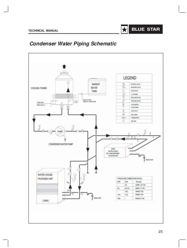
Blue Star Package Units
Wrg 5531 Piping Diagram Ac

Water Refrigerant Hybrid Ac Cooling Post
