Lighting Ballast Wiring Diagram 208

Hid Ballast Wiring Diagrams For Metal Halide And High

Hid Ballast Wiring Diagrams For Metal Halide And High

400 Watt Metal Halide Ballast Wiring Chaochui Co

Individual ballast wires each connect to a lampholder on one side of each tube.
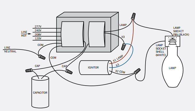
Lighting ballast wiring diagram 208. Normally commercial high bay lighting has changable taps on the ballast to serve it at any voltage you want. Turn off supply voltage at breaker before accessing fixture wiring compartment. It reveals the components of the circuit as streamlined forms and the power and also signal links in between the gadgets. They are also one of the charter products of the nema premium ballast program.
Refer to wiring diagram on ballast label for proper component connections typical connections illustrated above. Facturer is listed for ac ballasts that have unique wiring arrangements. The service will also need to be 3 phase 208 volt normally or you should wire the ballast for 240 volts normally if a single phase service. Led drivers and fluorescent ballasts marked with a dash between the voltage will function in that range.
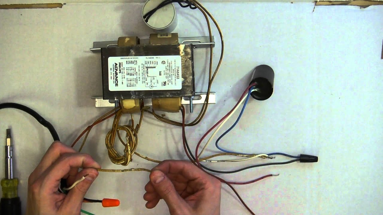
How to wire a replacement ballast with different wiring. Assortment of fluorescent ballast wiring diagram. Individual vs common ballast wires. Can anybody school me on a 208v lighting system or 208v systems period.
A quad tap ballast would be marked 120v 208v 240v 277v and would have to be set up for the correct line voltage. Field wiring connections should only be made by qualified personnel. For hi hx ballasts with model number 5xx suffix such as m0100 71c 511 1. Of lamps input volts.
This must have not been the case in your situation. Customer question wiring a multi tap ballast. Before installation make certain supply and ballast voltages are compatible. I suspect the wiring is not as simple as described.
Experts are full of valuable knowledge and are ready to help. A wiring diagram is a streamlined standard pictorial representation of an electric circuit. Follow the colore coded wiring diagram was the recommendation yet after connecting all like colors on the new ballast to the fixture all i got was a delayed dim light at the base of each fluorescent bulb. Photo control wiring diagram 208v 240v 277v 480v blk red line line photo control wht lampload red or wht blk blk yel compact fluorescent ballast wiring diagrams 1 1 lamp 2 2 lamp quad volt ballasts are factory wired for 277v input.
No neutral is required and yes it will need to be a 2 pole breaker. Diagrams for specific situations can be located within this pdf file by using the following methods. Electricians usually refer to a light bulb as a lamp. 1 using the navigation window use the navigation window and select the emergency ballast for which the diagram is needed then scroll through the list of applications to find the.
On this page we will refer to a fluorescent light bulb as a lamp or tube. Light bulb manufacturers use the term lamp when referring to fluorescent lights.
240v Ballast Wiring Diagram Wiring Schematic Diagram

480v Ballast Wiring Diagram Wiring Library Diagram A5

Relb 2s40 N Wiring Diagram Ballast Advance To Electronic

How To Bypass A Ballast 1000bulbs Com

240 Volt 3 Wire Split Phase Ballast Bypass Wiring

480 Volt Lighting Wiring Diagram Wiring Schematic Diagram

B214pu115s50a Dimming Ballast

277 Volt Wiring Diagram Wiring Library

Rss696at 208 347v Allanson Rss Sign Ballasts
Metal Halide Fixtures Mike Holt Code Forum
How To Wire Ballast 1

Relb 2s40 N Wiring Diagram Ballast Advance To Electronic
Advance High Pressure Sodium Hid Ballast Kit 100 Max Lamp

100 W Metal Halide Ballast Kit Keystone Mh 100x Q Kit Quad

480 Volt Lighting Wiring Diagram Wiring Schematic Diagram

100 Watt Mh Quad Tap Ballast Kt

400 W Metal Halide Ballast Kit Keystone Mh 400a P Hp Kit 5

Phillips Ballast Wiring Diagram Single Phase 208 Wiring
