Burglar Alarm Schematic

Automatic Intruder Alarm Circuit Diagram

Simple Burglar Alarm In 2019 Alarm Systems For Home
Burglar Alarm Project With Circuit Diagram
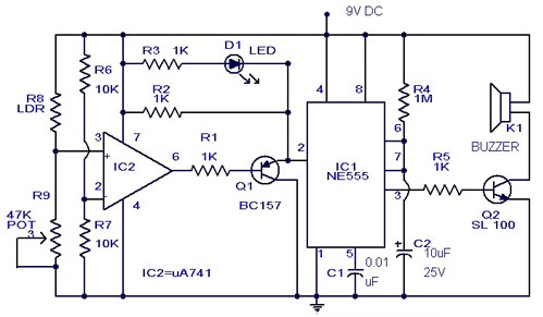
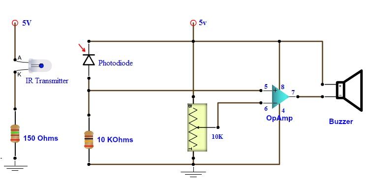
Here is the simple and efficient burglar alarm using photo transistor and an op amp comparator.
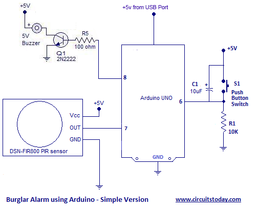
Burglar alarm schematic. This circuit works with battery 9v a piece is very small. For the work happens independently dont be under house electricity. This intruder alarm or burglar alarm circuit is based on pir sensor um3561 and speaker. Most of the home security systems are very expensive.
This allows charging the backup battery arming and disarming the system sounding alarm conditions and communicating with a central station. Share on tumblr we need safety and security for our valuable things to protect our property simple and robust security alarm circuit designed by using easily available components. Many security alarms were designed and published in electronics hub. Other than the family dog the most basic burglar alarm is a simple electric circuit built into an entry way.
Home security alarm system circuit diagram gallery of electronic circuits and projects providing lot of diy circuit diagrams robotics microcontroller projects electronic development tools. Picture of our burglar alarm project. Pir sensor used here to detect body motion and um3561 speaker to produce police siren after any movement detection. With the help of this project an inexpensive burglar alarm system can be implemented.
We know the laser light amplification by stimulated emission of radiation light has high strength focused light rays in this project we have used that laser light as a fence. The circuit will make a noise to warn work as soon as detect which be switch model usual close the circuit or aluminum eliminated separate. In any circuit whether its powering a flashlight or a computer electricity only flows when you give it a path between two points of opposite charge. It is different from others burglar alarm systems because is a very simple diy project and can offer you great satisfaction.
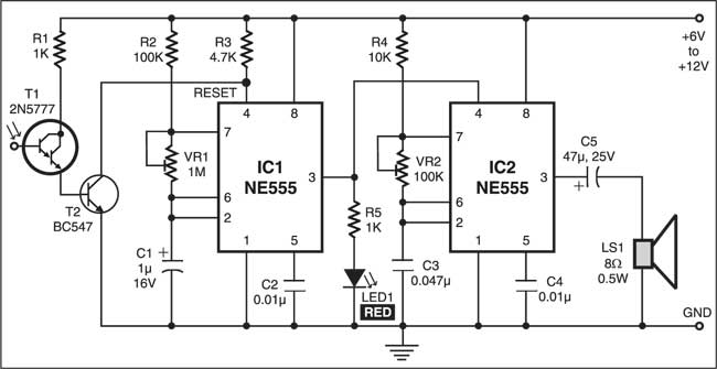
Click here for a detailed circuit description this is a simple single zone burglar alarm circuit. Ic 555 is connected as comparator with pin 6 connected with positive supply the output goes high 1 when the trigger pin 2 is at lower than 13 level of the supply voltage conversely the output goes low 0 when it is above 13. Burglar alarm model the circuit closes. To turn the electricity on or off you.
Its features include automatic exit and entry delays and a timed bellsiren cut off. Hardwired home security systems need some basic alarm system wiring for main panel operation. This burglar alarm system circuit is using a infrared proximity detector that triggers an alarm when the rays falling on its sensor are interrupted. Its designed to be used with the usual types of normally closed input devices such as magnetic reed contacts micro switches foil tape and pirs.

Modular Burglar Alarm

Burglar Alarm System Project
Intruder Alarm Circuit Diagram Using Opamp And Ic 555

Pir Burglar Alarm Circuit

Infrared Burglar Alarm Detailed Circuit Diagram Available

9 Burglar Alarm Circuit Ideas Electronics Projects Circuits

How To Make A Burglar Alarm Circuit For Your Home Security
Burglar Alarm Circuit And Projects Diy

9 Burglar Alarm Circuit Ideas Electronics Projects Circuits

Multi Zone Transistor Based Burglar Alarm Circuit Diagram

Burglar Alarm Security Circuit For Home By Ic 555 Circuits99

Simple Burglar Alarm Circuit Diagram In 2019 Circuit
Burglar Alarm Circuit Using Ic 555 Gadgetronicx

Car Burglar Alarm Using Two 555 Timers Electronics Area
Sensitive Optical Burglar Alarm Circuit Full Project Available
How To Make Best Burglar Alarm Circuit

How To Build A One Time Only Burglar Alarm Circuit

Sensitive Optical Burglar Alarm Electronics Project
