Boyer Electronic Ignition Wiring Diagram

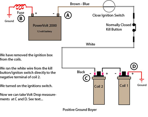
Vintage Bike Magazine How To Troubleshoot A Boyer Ignition

Wiring Diagram For Triumph Bsa With Boyer Ignition Tut
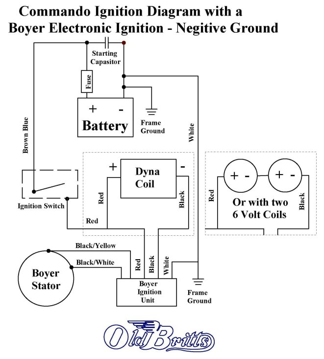
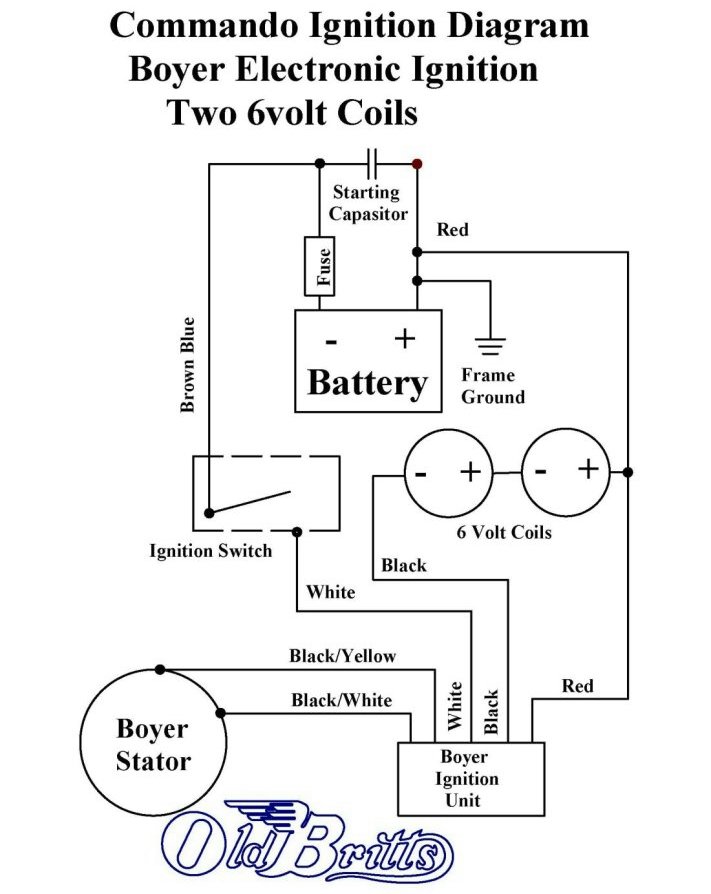
Old Britts Simplified Wiring Diagrams

If so all connections should be.
Boyer electronic ignition wiring diagram. How can we help. Diagram by tim dodge. Wiring diagram for triumphbsa with boyer ignition. Ignition coils wiring battery in different positions.
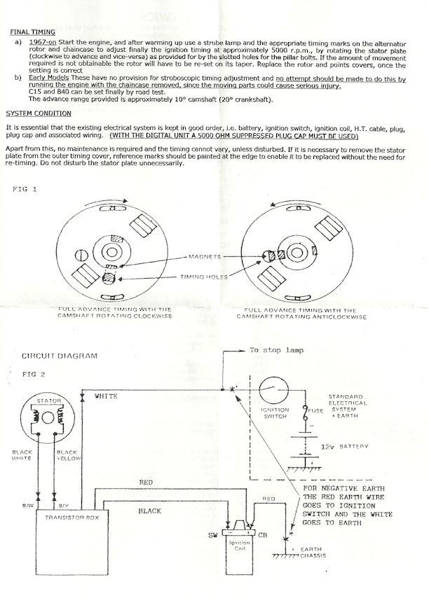
Electronic ignition system for unit construction bsa c15 and b40 models equipped with distributor type ignition and converted to 12 volt operation positive earth with or without a battery 267k kit00062 box00016 micro mk3 electronic ignition system for kawasaki kh250 3 cylinder two strokes and various models using the same basic engine 325k. With a combination of modern technology a sound knowledge of ignition requirements and highly competent technical staff boyer bransden have supplied special ignition systems for many applications. The boyer electronic ignition system uses a concept called wasted spark with the two coils wired in series they are energized together on every rotation of the camshaft. No condensers needed and the 12.
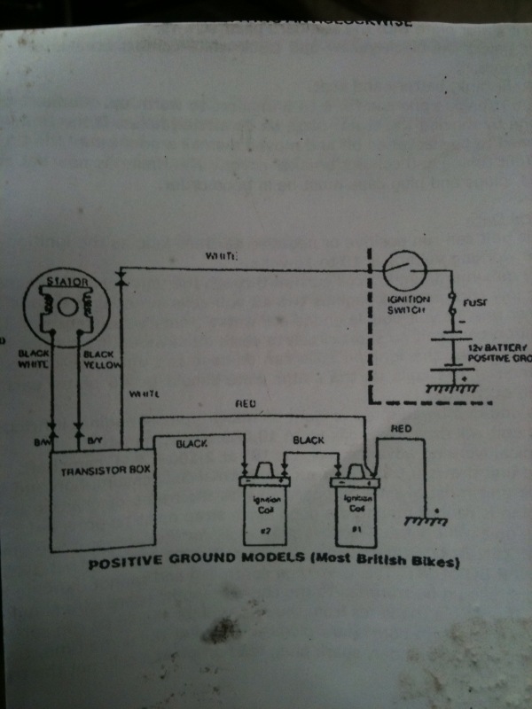
Installed the boyer electronic ignition after messing with the points and unsuccessfully trying to time each side i decided to take the advice of many many other vintage bike owners and ditch the archaic lucas ignition and go with an updated electronic ignition. Click here for negative ground wiring diagram. Youll note in the wiring diagrams below that the ballast resistor and condensers have been removed as part of the conversion to electronic ignition. Diagram of positive ground triumph wiring for boyer ignition.
19 connect the white blue wire the one removed from the ballast resistor to the white wire from the transistor box. This diagram is not to be reproduced or used on any site without permission by rask cycle. 18 connect the black wire from the transistor box to the terminal of the right hand ignition coil. Thus it may be necessary to modify the length of some wires to complete the installation.
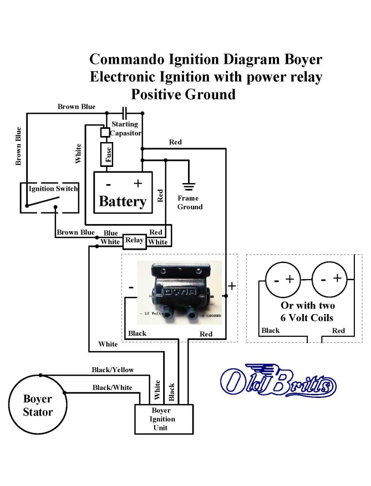
Rask cycle tech tips. Step one was to study the wiring diagram. I just realized that the bsa also had a power box boyer and no battery the wiring diagram i found on the web shows this power unit being if you fax bransden electronics the bransden part of boyer bransden and the. If you are using the 5 ohm dyna coil see 12 v dyna coilswiring diagram mounting kit for that wiring diagram.
The boyer and podtronics pairing is probably the most common set of upgrades to a bike. High quality png 30661841. Today boyer bransden produce one of the most efficient ignition systems in the world. Good quality jpg 1280769.
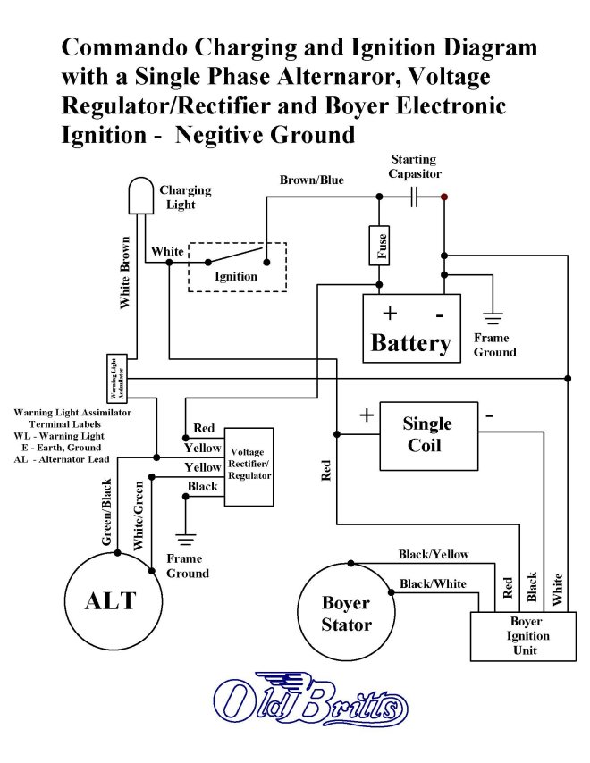
This diagram includes both the boyer electronic ignition and the podtronics combined regulatorrectifier unit. All systems are carefully hand built in the uk and we pride ourselves on supplying hardy products that last.
Old Britts Simplified Wiring Diagrams
Me And This Motorcycle Installed The Boyer Electronic Ignition

Bullet Boyer Ignition Wiring Diagram Google Search

Boyer 101

Lowbrow Customs Motorcycle Wiring Diagram Boyer

Ntnoa Information Library Engine
Boyer Ign Sysytem
Vintage Bike Magazine How To Troubleshoot A Boyer Ignition

6 Volt Positive Ground Wiring Diagram
Old Britts Simplified Wiring Diagrams

Ajs Matchless Lightweight Fitting Boyer Bransden Electronic
Boyer Electronic Ignition Triumph Bsa 1 Cylinder Mk Iv 12v
Old Britts Simplified Wiring Diagrams

Dyna Electronic Ignition Wiring Diagram Wiring Library

Vintage Bike Magazine How To Troubleshoot A Boyer Ignition

Boyer Electronic Ignition Mk Iv 12v Bsa Triumph 3 Cylinder

Boyer Ignition Troubleshooting

Triumph Wiring Diagram With Boyer Wiring Diagram
