Am Fm Radio Circuit Diagram

Am Fm Radio Receiver Circuit Using Ta8122
Fm Receiver Electronics Circuit With Full Explanation
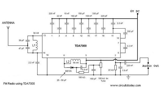
Single Chip Fm Radio Circuit With Diagram Using Tda 7000 Ic

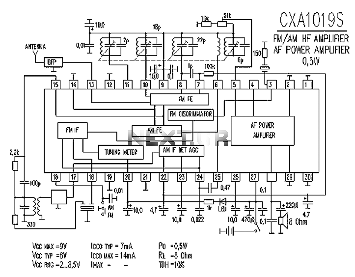
Cxa1019 fm radio circuit diagram.
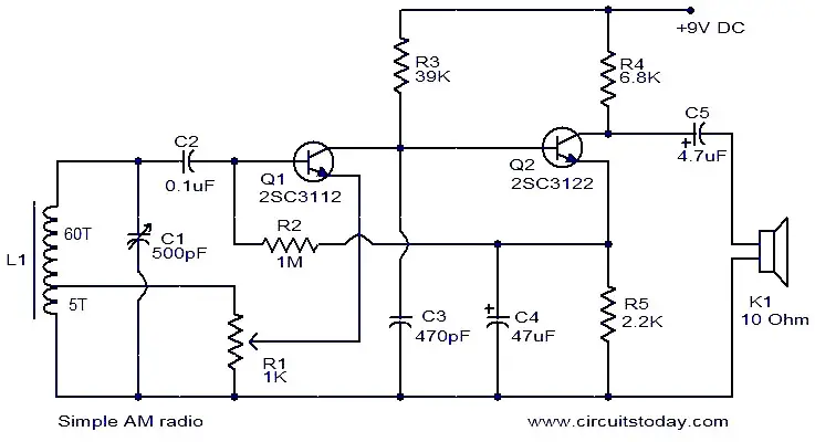
Am fm radio circuit diagram. As can be seen in the given circuit diagram the design is as simple as it can be just a couple of general purpose transistors and a few other passive components for configuring what looks like a nice little am radio receiver unit. Cxa1019 fm radio cxa1019 is a one chip fmam radio ic designed for radio cassette tape recorders and headphone tape recorders and cxa1019s has the following skip to main content. The signals are capacitor coupled through c2. The main principle of this circuit is to tune the circuit to the nearest frequency using the tank circuit.
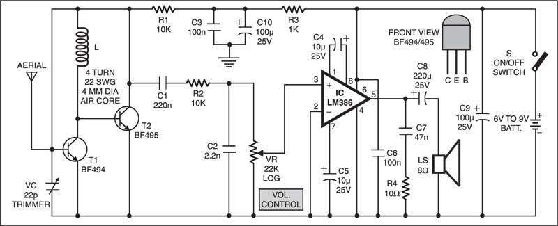
Coil l1 and the trimmer capacito form the tuned tank circuit to tune the receiver to the best fm station with strong signals. Radio is the reception of electromagnetic wave through air. It uses only 2 transistors and few passive components which makes is very easy to be constructed. Transistor bf495 t2 together with a 10k resistor r1 coil l 22pf variable capacitor vc and internal capacitances of transistor bf494 t1 comprises the colpitts oscillatorthe resonance frequency of this oscillator is set by trimmer vc to the frequency of the transmitting.
In previous article about how to make a radio we have discussed a simple crystal radio receiver circuit. Although the circuit is very simple it functions very well without external antenna or ground connection. Fm receiver circuit e xplanation. It is similar in principle to the zn414 radio ic which is now replaced by the mk484.
Fm radio circuit principle. All general purpose transistors should work in this circuit you can use bc549 transistors for this circuit. Heres a simple fm receiver with minimum components for local fm reception. Tiny fm radio receiver circuit schematic.
This is the circuit diagram of mini am radio receiver. The schematic mentioned here is also a simple am radio circuit but it is not using a crystal it is using high gain preamplifier stage of transistor bc 549. Wiring diagrams for car radio. The fm receiver section has two rf transistors t1 and t2 to detect the frequency modulated signals.
Car stereo wiring diagrams one of the challenges diy installers face is finding the correct installation diagrams for car stereos. Below i have put together some of the best free sources for car stereo wiring diagrams and wiring colors. A simple fm radio circuit with diagram and schematic using ic tda 7000.

Am Fm Radio Fm Receiver Circuit Diagram Using Tea5710

Small Fm Radio Circuit
Simple Am Radio Electronic Circuits And Diagrams
Am Radio Circuit Rf Circuits Next Gr
Cd9088cb Am Fm Radio Kit On Ebay Circuit Diagram
An7025k 7025s Am Fm Stereo Radio Circuit Audio Circuit

Use La1800 Portable Am And Fm Radio Diagrams Circuit
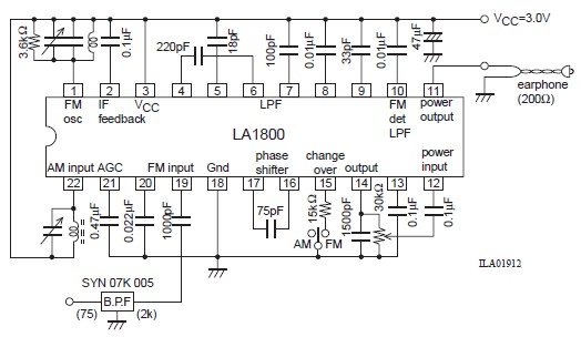
La1800 Portable Am Fm Radio Circuit Design Electronic Project

Schematic Diagram Of Fm Radio Wiring Diagrams
La1810 1811 Am Fm Stereo Radio Circuit Audio Circuit

Pc Fm Radio Circuit

Tda1083 Am Radio Circuit Schematic
Cxa1019 Fm Radio Circuit Diagram Electronic Circuits
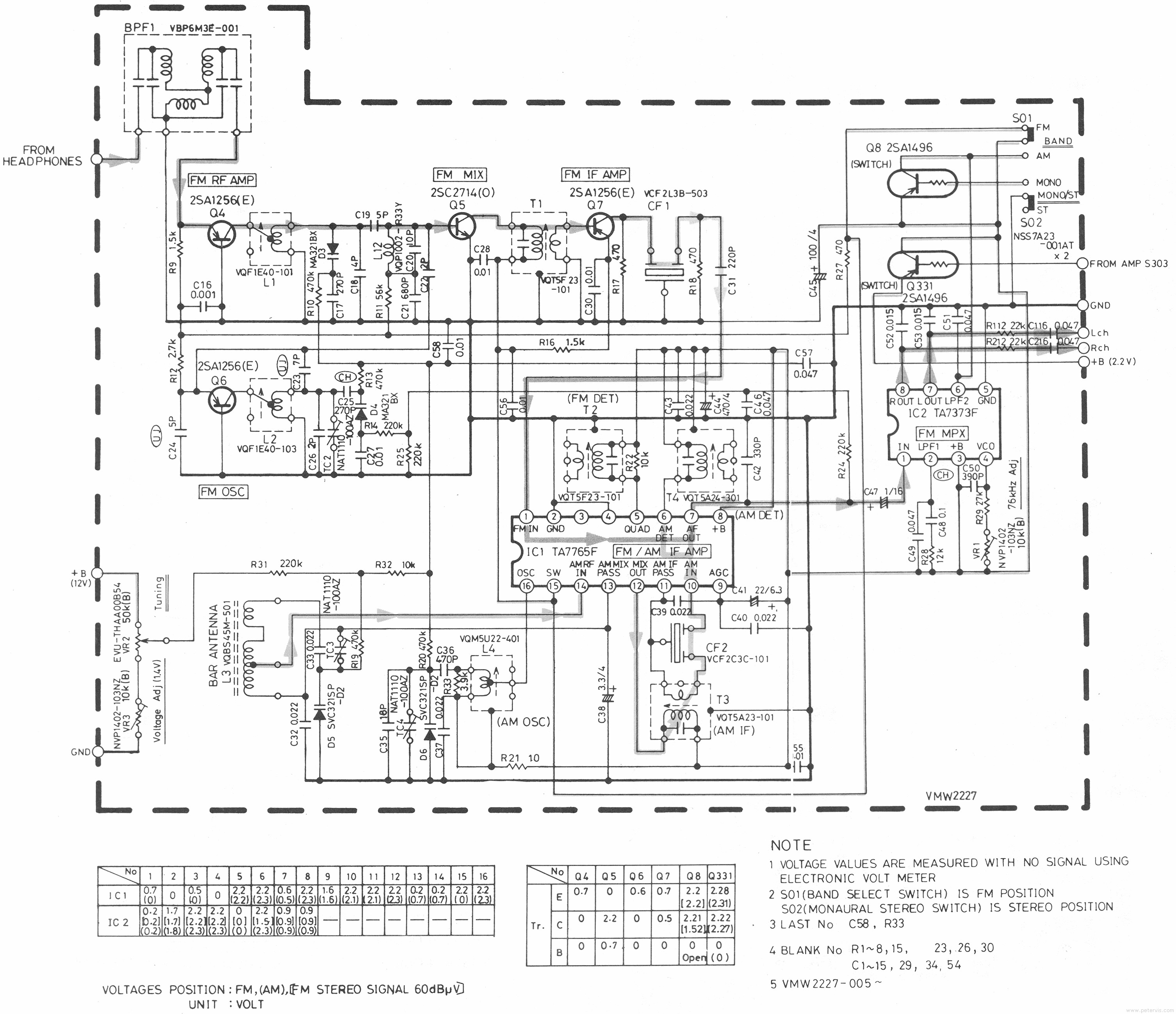
Jvc Cx F7k Am Fm Radio Circuit
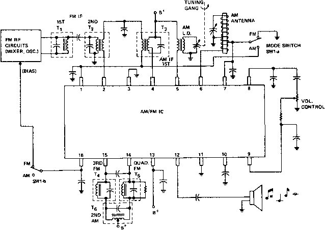
Figure 1 From A Single Chip Am Fm Integrated Circuit Radio

Receiver Circuit Page 4 Rf Circuits Next Gr

Am Fm Varicap Radio Receiver

Fm If Mw Radio Receiver Circuit Using La1260 Integrated Circuit
